
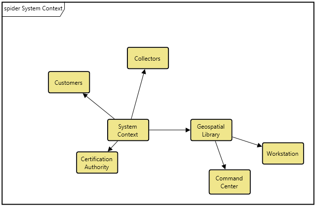
The Spider diagram provides a complete contextual view of a set of entities and their interrelationships. Part of the general representation set, this diagram blends concepts present in an ER diagram (displaying relationships relative to an entity of interest) with concepts of a Hierarchy diagram (showing multiple levels of relationships). Unlike a Hierarchy diagram, each entity is represented once and only once. In addition, the freeform presentation does not artificially imply a hierarchical relationship that may not exist. The result is an extremely powerful representation neither traditional nor SysML for analysis and communication.
A Spider diagram is opened on the combination of an entity and a hierarchy definition. The entity defines the starting point for the diagram. The hierarchy definition specifies the relations (and optionally target classes) to traverse when building the spider diagram. The diagram will open to the number of levels specified with each entity encountered displayed on the diagram once and only once. The relationships between the entities are then shown as connecting lines.
|
CAUTION! |
Entities are drawn only once on the diagram, potentially representing multiple relationships. If you select a node on a spider diagram and ask to remove it, you will remove all relationships which connect it to entities on the diagram. |
The spider diagram is a free-form diagram. The diagram supports many different layout types selectable from the diagram options and the layout pull down. Switch between layouts to select your preferred starting point and then customize node positions as desired. Individual nodes can be moved anywhere on the diagram. In addition, individual relation line labels can be moved along the relationship line.
Toolbox Properties
In addition to the classic diagram options, the spider diagram settings include:
-
Use Orthogonal Lines - controls whether orthogonal lines or direct lines are used to connect nodes on the diagram.
-
Levels - controls the initial number of levels to show on the diagram. Individual nodes can then be expanded or collapsed, as desired.
-
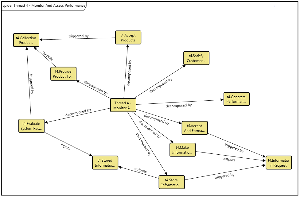
Show Relationship Labels - controls whether relationship names (aliases, if defined) are displayed on the relationship lines indicating the relationship between the connected nodes. When the objective is simply to understand the connectivity of entities (but not the specific nature of the interrelationships), toggling off the display of relationship names will minimize clutter on the diagram and increase readability. Note that the initial value for this setting is drawn from the specified hierarchy definition and is then controlled by the diagram option.
Toolbox Insert
The constructs tab allows you to quickly decorate your spider diagram, while the all entities tab enables you to relate your diagram entities to the remainder of your system definition.
Utilities
-
Image - drop onto the diagram to insert a new picture
-
Note - drop onto the diagram to insert a new note (descriptive text in a note icon)
-
Shapes - drag one of the shapes from the toolbox and drop onto the diagram to insert a new shape
All Entities - all classes and entities in the system model, allowing you to drag any entity on top of a diagram node to establish relationships with the balance of your system model
Context Menu Commands
-
-
All Relationships
-
Behavior Impact of Physical Change
-
Classification
-
Function
-
Interface
-
Organization
-
Package
-
Physical
-
Requirement
-
Traceability
-
Use Case
-
Verification Tree
-
Work Breakdown Structure
-
Custom
-
-
Arrange
Tips and Tricks
-
Holding down control while double-clicking a node is a shortcut for expand / collapse. If the node is collapsed, it will expand it by a single level. If it is expanded, it will collapse the node.
-
Adding entities to a spider diagram is best handled by dragging entities onto nodes from the diagram toolbox to establish the desired relationships.
-
When following a single relationship (for example, a physical hierarchy or a functional hierarchy), toggle off the display of relationship names. The semantic is clear and the additional text can clutter the diagram. When multiple relationships are being followed, ensure the show relationship names option is toggled on so that the nature of each relationship is understood.
-
In general, it is better to move nodes first and then reposition labels as desired. Otherwise, as you move nodes, the connecting lines will shift as well, potentially forcing you to then manually reposition the label.