
The Physical Block diagram is a traditional systems engineering block-and-line diagram representing the physical links that connect components within a system or system segment. Part of the physical architecture representation set, the physical block diagram is the more detailed view of the architecture composition.
The Physical Block diagram is available for entities in the Component class (as well as any other subclasses of ImplementationUnit).
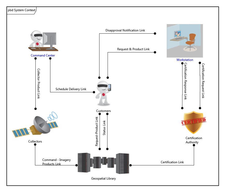
In this classic variant of a component wiring diagram, the children of the component are shown as nodes on the diagram. Lines connecting to a node reflect the links (the physical connections) connected to the node. If the link does not connect to another component in the system model, the link is drawn as an unterminated line (an obvious diagnostic for resolution). If the link connects to two components within the decomposition, both ends of the line are connected to classic nodes. If one end of the link exists outside the composition of this component (if the link is an external connection), the external component is also shown on the diagram and connects to the link to show the full context. To help distinguish external components which link to subcomponents from the subcomponents themselves, external components are drawn with a grey background by default.
The physical block diagram is a free-form diagram. GENESYS begins with a simple layout for the nodes but offers several layout options to choose from. Then you can customize node positions as desired. Individual lines can be repositioned as well. Drag the handle at the connection point with the node to control where the line connects to the node. Drag a handle at a bend in the line to move that line segment. Individual labels can be resized and moved along the lines.
|
NOTE: |
The GENESYS schema limits a link to connect a maximum of two components. In a hub or bus model, the hub or bus itself is in reality a component and should be modeled as a first class component in order to properly represent the hub/bus and its links to other components. |
Toolbox Properties
The physical block diagram settings do not include any special diagram options beyond the classic diagram options.
-
Use Orthogonal Lines - controls whether orthogonal lines or direct lines are used to connect nodes on the diagram.
Toolbox Insert
The constructs and key entities Toolbox tabs allow you to quickly develop your physical block diagram, while the all entities tab enables you to relate your components and links to the remainder of your system definition.
Constructs
-
New Child - drop onto the diagram background to create a new block (component) as part of the node composition (built from)
-
Children - drop onto the diagram background to add an existing block (component) as part of the node composition (built from)
-
New Connection - drop onto any diagram node to create a new connection (link) that connects to the node
-
Connections - drop onto any diagram node to relate an existing connection (link) using the connects to relation
Utilities
-
Image - drop onto the diagram to insert a new picture
-
Note - drop onto the diagram to insert a new note (descriptive text in a note icon)
-
Shapes - drag one of the shapes from the toolbox and drop onto the diagram to insert a new shape
Key Entities
-
Component - drop an existing component onto the diagram background to add an existing component as part of the diagram composition (built from)
-
Item - drop an existing item onto a link to relate it to the entity using the transferred by relation
-
Link - drop an existing link onto a node to relate it to the node using the connects to relation
All Entities - all classes and entities in the system model, allowing you to drag any entity on top of a diagram node to establish relationships with the balance of your system model
Context Menu Commands
-
Arrange
-
Submenu listing entities
Tips and Tricks
-
In general, it is better to move nodes first and then reposition lines and labels as desired. Otherwise, as you move nodes, the connecting lines will shift as well, potentially forcing you to then manually reposition the line or label.
-
Once you get the nodes in place use the Transform command Line Routing >> Route All Lines Orthogonally or select the lines that are not correct and use Line Routing >> Route Selected Lines Orthogonally.
-
Using a diagram shape on block diagrams is a good way to graphically indicate clusters.
-
The lines on a block diagram represent first class entities. You can drag-drop these entities onto nodes to connect them, or you can drag-drop nodes onto the line. Remember that just dragging an image moves it. To drag-drop, hold down the control key while dragging or right-click and drag.