
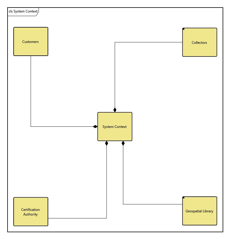
Bridging the gap between systems and software engineering, the class diagram displays the static structure and composition of a system. It shows the systems classes and optionally displays their attributes, operations, and relationships among the entities. Though most frequently used to reflect software design architecture, the flexibility of the class diagram makes it a useful addition to a library of integrated system representations.
-
Dependency. A dependency relationship exists between two entities if changes to the definition of one entity may cause changes to the other. Essentially, one entity requires, needs, or depends on the other for specification or implementation.
-
Association. An association is an abstract term that can represent any relationship between two classes. An association can be either bidirectional or unidirectional.
-
Aggregation. An aggregation shows the formation of a particular class as a result of one class being aggregated or built as a collection. For example, a course is an aggregation of students.
makes it a useful addition to a library of integrated system representations.
One of the primary benefits of this diagram is the ability to reflect different types of relationships between two or more entities within your system. The types of relationships include:
-
Composition. A composition is similar to the aggregation, with the difference being the emphasis on dependence. For example, a house is a composition of rooms. However, if the house ceased to exist, the rooms would no longer exist, as their existence is dependent on the existence of the house.
-
Generalization. A generalization relationship is a type of relationship that establishes an associated class as a child (subclass) of another by assuming inheritance of the functionalities of the parent (superclass). The child class is considered a specialization of the parent class. For example, a cat would be a specialization of an animal, where a cat is the child inheriting the functionality of the parent animal.
The class diagram is a free-form diagram. GENESYS begins with a simple layout for the nodes but offers several layout options to choose from. Then you can customize node positions as desired. Individual lines can be repositioned as well. Drag the handle at the connection point with the node to control where the line connects to the node. Drag a handle at a bend in the line to move that line segment.
Diagram Options
In addition to the classic diagram options, the state transition diagram settings include:
-
Use Orthogonal Lines - controls whether orthogonal lines or direct lines are used to connect nodes on the diagram.
-
Levels - controls the number of levels being shown for the diagram.
Diagram Toolbox
The constructs and key entities tabs allow you to quickly develop your use case model, while the all entities tab enables you to relate your state transition model to the remainder of your system definition.
Constructs
-
New Class - drop onto any diagram node to create a new related entity (which relationship created is based on further selections)
-
Class - drop onto any diagram node to edit the related entities (which relationship created is based on further selections)
-
New Association - drop onto any diagram node to create a new association to another Component (start of UMLAssociation)
-
New Dependency - drop onto any diagram node to create a new dependency to another Component (start of UMLAssociation)
Utilities
-
Image - drop onto the diagram to insert a new picture
-
Note - drop onto the diagram to insert a new note (descriptive text in a note icon)
-
Shapes - drag one of the shapes from the toolbox and drop onto the diagram to insert a new shape
Key Entities
-
Component - drop an existing component onto a node to establish any valid relationship
-
UMLAssociation - drop an existing UML Association onto a node to establish a valid relationship
All Entities - all classes and entities in the system model, allowing you to drag any entity on top of a diagram node to establish relationships with the balance of your system model
Context Menu Commands
-
Edit Children (with Component selected)
-
Edit Part Multiplicity (with built from/built in relation selected)
-
Toggle Whole Multiplicity (with built from/built in relation selected)
-
Arrange
-
-
Submenu listing entities
-
Tips and Tricks
-
In general, it is better to move nodes first and then reposition lines and labels as desired. Otherwise, as you move nodes, the connecting lines will shift as well, potentially forcing you to then manually reposition the line or label.
-
Using a diagram shape in conjunction on block diagrams is a good way to graphically indicate clusters.
-
The lines on a class diagram may represent first class entities. You can drag-drop these entities onto nodes to connect them, or you can drag-drop nodes onto the line. Remember that just dragging an image moves it. To drag-drop, hold down the control key while dragging or right-click and drag.