
In SysML, blocks are generic units systems, components, items, conceptual entities, and logical abstractions. Block definition diagrams (BDDs) are used to define blocks in terms of their structure, classification, and behavior. The BDD is available for entities in the Component class (as well as any other subclasses of ImplementationUnit).
When put into practice and mapped to our STRATA methodology, blocks are used to represent implementation units (hardware, software, and people). Block definition diagrams are used to define the composition and the classification of implementation units.
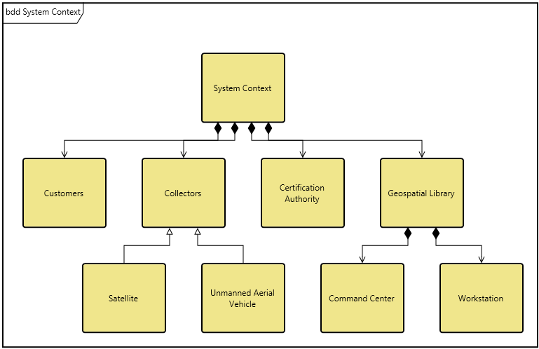
The BDD represents the composition structure of systems, components, items, conceptual entities, and logical abstractions as well as the inheritance structure of systems, components, items, conceptual entities, and logical abstractions. In addition to the appropriate line decorations to reflect specialization (open triangle), aggregation (open diamond), and composition (filled diamond), the BDD displays part roles and part multiplicity. Optionally, the diagram can display the relationship names on the connection lines to increase the communication value.
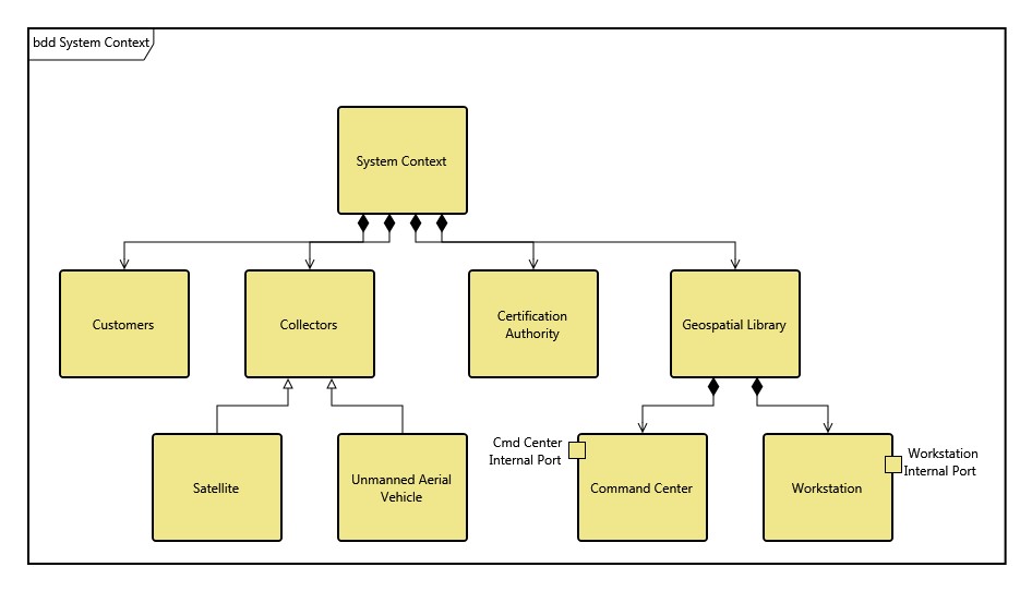
The BDD can optionally show ports on nodes in their nested structure. This allows you to visually represent both the components and their available connection ports.
The BDD uses a structured layout with specific movement rules for each node.
Multiple node representations are supported by block diagrams. In addition to the entity name, you will frequently see some combination of the following fields:
-
Operations - behavioral aspects allocated to the block. Operations describe synchronous interactions where the requester waits for the request to be handled. Operations reflect a subset of the allocated functions (both by definition and by the fact that users classically represent only a subset of operations on the node). This has been captured as the operations attribute. Note that for consistency, any operation listed here should also be reflected in the collection of functions allocated to this component.
-
Values - represent quantifiable characteristics of a block such as physical and performance characteristics weight, reliability, etc. This is captured in the values attribute.
-
Parts - are the hierarchical composition of the block (the children). This is captured using the built from relationship.
|
NOTE: |
A good reference for further information on BDDs is chapter 7 of A Practical Guide to SysML: The Systems Modeling Language by Sanford Friedenthal, Alan Moore, and Rick Steiner (2012). |
Toolbox Properties
In addition to the classic diagram options, the BDD settings include:
-
Use Orthogonal Lines - controls whether orthogonal lines or direct lines are used to connect nodes on the diagram.
-
Show Role Names - controls whether the part role for the node is shown on the diagram.
-
Show Ports - controls whether the ports are displayed on the diagram.
-
Hide Port Keywords - controls whether the port key words, <<full>> or <<proxy>>, are displayed.
Toolbox Insert
The constructs and key entities tabs allow you to quickly develop your block definition, while the all entities tab enables you to relate your blocks to the remainder of your system definition.
Constructs
-
New Part - drop onto any diagram node to create a new block (component) as part of the node composition (built from).
-
Parts - drop onto any diagram node to relate an existing block (component) as part of the node composition (built from).
-
New Specialization - drop onto any diagram node to create a new specialization.
-
Specializations - drop onto any diagram node to relate an existing specialization.
-
New Port - drop onto any diagram node to create a new port.
-
Port - drop onto any diagram node to relate an existing port.
Utilities
-
Image - drop onto the diagram to insert a new picture
-
Note - drop onto the diagram to insert a new note (descriptive text in a note icon)
-
Shapes - drag one of the shapes from the toolbox and drop onto the diagram to insert a new shape
Key Entities
-
Component - drop an existing component onto a node to establish any valid relationship. Most often, this will be composition (built from).
-
Port - drop an existing port onto a node to establish any valid relationship.
All Entities - all classes and entities in the system model, allowing you to drag any entity on top of a diagram node to establish relationships with the balance of your system model.
Context Menu Commands
-
Arrange
-
-
Submenu listing entities
-
Tips and Tricks
To communicate the full technical depth of the block structure, BDDs classically include far more content per node than other diagrams. Make liberal use of the ability to specify different icon templates for each node, using more complete templates where operations/values/ports are desired and lesser templates where they are not. Not only does this tighten the diagram, it helps focus attention on the critical aspects you are seeking to emphasize.