
The Hierarchy diagram represents the relationships between several layers of entities. There is no pre-defined semantic for a hierarchy, allowing the user to define the specific set of relationships to deliver the desired representation and insight in a traditional representation. Sample uses include functional, physical, and traceability hierarchy views. Part of the general representation set, Hierarchy diagrams are available for all entities.
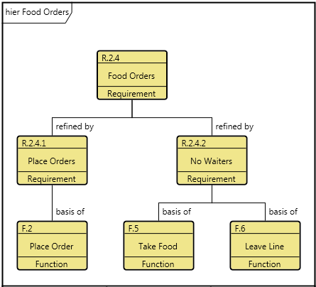
A Hierarchy diagram is opened on the combination of an entity and a hierarchy definition. The entity defines the starting point for the diagram. The hierarchy definition specifies the relations (and optionally target classes) to traverse when building the Hierarchy diagram. In building the diagram, GENESYS starts with the top-level entity and checks to see if any of the specified relationships have targets of the specified target classes. If so, these targets become children of the top-level entity and are displayed on the second level of the diagram. The children of the entities on the second level are then determined. This process continues until the lowest level entities have no targets in the specified set of relations. Individual entities are shown as nodes with the relationships between the entities shown as connecting lines.
The Hierarchy diagram uses a structured layout with specific movement rules for each node. In a hierarchical format, if the same entity is encountered multiple times when traversing the database, it is shown on the diagram multiple times. This presents a clean representation and avoids the "string art" of crossing lines. When an entity appears in multiple places on the diagram, a small black square appears in the upper right corner of the icon. In this event, GENESYS proceeds to expand the first occurrence of the entity.
A node with a black square in the upper left indicates that there is more information to display. This can occur if there are more relationships to traverse than the number of levels specified for the diagram. This can also occur if you collapse an existing node to hide the nodes beneath it. Individual nodes can be expanded or collapsed as desired to tailor the representation.
Toolbox Properties
In addition to the classic diagram options, the Hierarchy diagram settings include:
-
Levels - controls the number of levels being shown for the hierarchy.
-
Use Orthogonal Lines - controls whether orthogonal lines or direct lines are used to connect nodes on the diagram.
-
Show Relationship Labels - controls whether relationship names (aliases, if defined) are displayed on the relationship lines indicating the relationship between the connected nodes. When the objective is simply to understand the connectivity of entities (but not the specific nature of the interrelationships), toggling off the display of relationship names will minimize clutter on the diagram and increase readability. Note that the initial value for this setting is drawn from the specified hierarchy definition and is then controlled by the diagram option in the toolbox.
Diagram Toolbox
The constructs tab allows you to quickly decorate your Hierarchy diagram, while the all entities tab enables you to relate your diagram entities to the remainder of your system definition.
Utilities
-
Image - drop onto the diagram to insert a new picture
-
Note - drop onto the diagram to insert a new note (descriptive text in a note icon)
-
Shapes - drag one of the shapes from the toolbox and drop onto the diagram to insert a new shape
All Entities - all classes and entities in the system model, allowing you to drag any entity on top of a diagram node to establish relationships with the balance of your system model
Context Menu Commands
-
Hierarchy Type
-
All Relationships
-
Behavior Impact of Physical Change
-
Classification
-
Function
-
Interface
-
Organization
-
Package
-
Physical
-
Requirement
-
Traceability
-
Use Case
-
Verification Tree
-
Work Breakdown Structure
-
Custom
-
-
Arrange
-
-
Submenus listing entities
-
Tips and Tricks
-
Holding down control while double-clicking a node is a shortcut for expand / collapse. If the node is collapsed, it will expand it by a single level. If it is expanded, it will collapse the node.
-
Adding entities to a Hierarchy diagram is best handled by dragging entities onto nodes from the diagram toolbox to establish the desired relationships.
-
When following a single relationship (for example, a physical hierarchy or a functional hierarchy), toggle off the display of relationship names. The semantic is clear and the additional text can clutter the diagram. When multiple relationships are being followed, ensure the show relationship names option on the hierarchy definition is toggled on so that the nature of each relationship is understood.
-
When adjusting the layout of the diagram, begin with the root of the tree and adjust from there. Children may be moved as you move the parent node.
-
While a Hierarchy diagram provides a clean, traditional representation, it often implies flow-down. It also can hide context since individual entities can be displayed in multiple locations on the same diagram. If understanding context is critical, consider using a Spider diagram instead. The spider diagram opens on the same combination of an entity and a hierarchy definition, but it is a free-form diagram in which each entity is represented once and only once.